




WE Metalworks logo with manufacturing and surface finishing tagline
CUSTOM OEM PROJECTS

Custom Metal Parts for OEM Manufacturing Projects

Custom metal components manufactured from customer drawings and CAD files, with machining, casting, forming, surface finishing and inspection coordinated around the finished part.

Custom Drawings Precision Machining Metal Forming Casting Surface Finishing OEM Production
SIMPLE TO COMPLEX

From Simple Metal Parts to Complex Multi-Axis Components

Not every OEM project requires complex geometry or advanced multi-axis machining. We also manufacture straightforward custom components such as plates, brackets, spacers, shafts, sleeves, housings and other drawing-based metal parts.

Whether your part is simple or highly complex, the project is reviewed according to the drawing, material, quantity, tolerances, surface finish and inspection requirements rather than complexity alone.
SIMPLE PARTS Plates · Brackets · Spacers · Shafts · Sleeves
TO
COMPLEX PARTS Housings · Multi-Surface Parts · Precision Assemblies
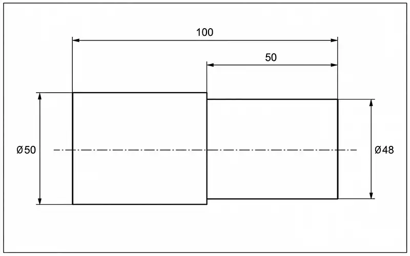
Stepped shaft engineering drawing with dimensions for simple machined part production
SIMPLE TURNED COMPONENT Stepped Shaft Drawing

This stepped shaft combines multiple turned diameters and shoulders, with dimensions and tolerance requirements defined directly by the customer drawing.
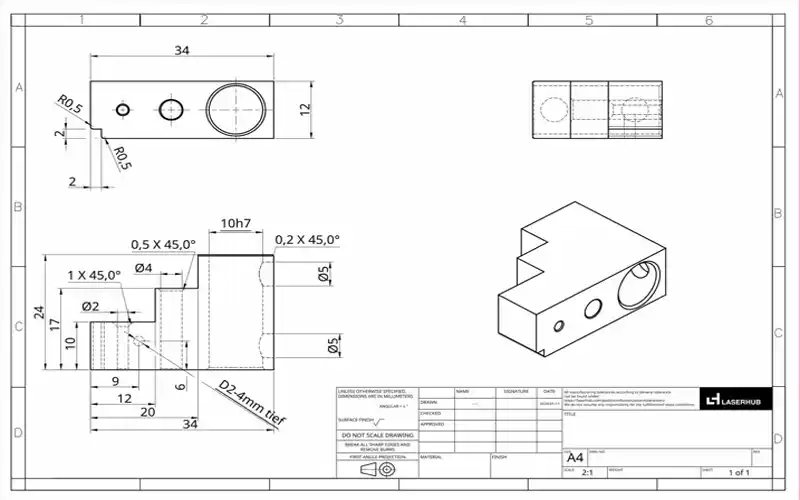
Simple clamp plate engineering drawing for custom OEM machining projects
COMPACT MACHINED BLOCK Clamp Block Drawing

This compact machined block combines stepped milling, multiple drilled and bored features, chamfers and small-radius transitions, with dimensions and tolerances defined directly by the customer drawing.

SIMPLE PARTS ARE WELCOME

A project does not need complex geometry to be a good fit. Clear drawings and practical manufacturing requirements are enough to start a technical review.

DRAWING-BASED OEM PROJECTS

Custom Projects from Customer Drawings & CAD Files

OEM projects begin with the customer's technical definition rather than a fixed product catalog. We review 2D drawings, 3D CAD files, tolerances, interfaces, material requirements and surface-finish specifications before establishing the manufacturing route.

The drawings below illustrate the technical information we work from when reviewing custom components, including dimensions, tolerances, material requirements, inspection points and finishing requirements.

Customer engineering drawing example for custom OEM metal part manufacturing review
01 CNC MACHINING

Precision CNC Machining

We manufacture drawing-defined metal parts using CNC milling and turning, with process planning based on part geometry, tolerances, material, quantity and inspection requirements.

Processes CNC Milling · CNC Turning
Typical Features Pockets · Bores · Threads · Profiles
Project Basis Drawing · Tolerance · Quantity · Inspection
Customer technical drawing example used for OEM machining and manufacturability review
02 ENGINEERING REVIEW

Drawing & Tolerance Review

Before production, we review customer drawings and CAD data for critical dimensions, tolerances, datum requirements, holes, threads, surface finish and inspection requirements.

Drawing Input 2D Drawings · 3D CAD Files
Review Focus Dimensions · Tolerances · Datums
Inspection Critical Features · Drawing Requirements
Customer part drawing example for custom metal machining material and tolerance review
03 MATERIAL OPTIONS

Metals for Custom Parts

Common materials for custom projects include aluminum alloys, stainless steels, carbon and alloy steels, brass, copper and titanium. Other grades can be reviewed according to part geometry, tolerance, quantity and finishing requirements.

Common Materials Aluminum · Stainless Steel · Steel
Additional Metals Brass · Copper · Titanium · Other Grades
Selection Basis Grade · Geometry · Finish · Quantity
Customer engineering drawing example for custom machining and surface finishing project review
04 INTEGRATED FINISHING

Machining + Surface Finishing

Machined parts can be coordinated with anodizing, electroplating, conversion coatings, passivation, electropolishing, PVD and mechanical finishing according to material compatibility and drawing requirements.

Manufacturing Machining · Forming · Casting · Forging
Finishing Anodizing · Plating · Passivation · PVD
Project Delivery Machined + Finished Custom Parts
HAVE A DRAWING READY FOR REVIEW?

Send your 2D drawing or 3D CAD file together with material or target material, tolerances, quantity, surface-finish and inspection requirements for an initial manufacturing review.

MANUFACTURING ROUTE PLANNING

Manufacturing Routes Selected Around the Part

Custom OEM parts should not be forced into a single manufacturing process. Geometry, material, quantity, tolerance, surface condition and functional requirements are reviewed together before the production route is established.

Depending on the project, a part may be produced directly by one process or move through several coordinated operations before final surface finishing and inspection.

01 PRECISION MACHINING

CNC Machining

CNC machining is used for drawing-based components requiring controlled dimensions, machined interfaces, bores, pockets, threaded features and complex multi-surface geometry.

TYPICAL PROJECT FIT Housings · Plates · Shafts · Fixtures · Precision Components
02 SHEET & PLATE CUTTING

Laser Cutting

Laser cutting supports flat metal components and profiles where drawing-defined outlines, holes, slots and repeatable cut geometry are required from sheet or plate material.

TYPICAL PROJECT FIT Plates · Panels · Brackets · Profiles · Cut Components
03 REPEAT PRODUCTION

Metal Stamping

Stamping can be considered for repeat-volume sheet metal parts where geometry, material thickness and production quantity support a dedicated tooling-based manufacturing route.

TYPICAL PROJECT FIT Clips · Brackets · Covers · Formed Parts · Repeated Components
04 NEAR-NET-SHAPE COMPONENTS

Die Casting

Die casting can be used for suitable metal components with integrated walls, bosses, ribs and structural features, followed by secondary machining where critical interfaces require additional control.

TYPICAL PROJECT FIT Housings · Frames · Covers · Structural Cast Components
05 FORMED METAL COMPONENTS

Forging

Forging can be considered where the component geometry, material and mechanical requirements are better suited to a formed blank before machining and finishing operations are completed.

TYPICAL PROJECT FIT Structural Parts · Blanks · Load-Bearing Components
06 FINISHED PART DELIVERY

Surface Finishing Integration

Surface treatment can be coordinated after machining, casting, stamping or forging according to the material, appearance, corrosion-resistance and finished-part requirements.

PROJECT OPTIONS Anodizing · Plating · Conversion · PVD · Other Specified Finishes
PROCESS SELECTION STARTS WITH THE DRAWING

A simple part may require only one manufacturing operation, while a more complex project may combine casting or forming, CNC machining, surface finishing and final inspection. The route is selected around the finished-part requirements rather than process complexity alone.

ENGINEERING & QUALITY REQUIREMENTS

Quality Control Starts with Clear Technical Requirements

Custom OEM manufacturing depends on more than part geometry alone. Drawing revision, material, tolerances, surface requirements, functional interfaces and inspection points should be understood before the production route is released.

Requirements can be reviewed from the customer drawing, CAD model, specification notes and other project documents so manufacturing and inspection are aligned with the finished-part definition.

01 TECHNICAL DEFINITION

Drawing & CAD Review

2D drawings and 3D CAD files are reviewed together where both are provided, with attention to dimensions, interfaces, section views, notes and features that affect manufacturing or inspection.

Drawing Revision · CAD Model · Notes · Interfaces
02 MATERIAL REQUIREMENTS

Material & Specification Review

Material grade, temper, condition and other drawing-defined requirements should be confirmed where they affect machining, casting, forming, surface treatment or finished-part performance.

Grade · Alloy · Condition · Customer Specification
03 DIMENSIONAL CONTROL

Tolerances & GD&T

Critical dimensions, datums, position, flatness, perpendicularity, profile and other specified controls are reviewed according to their effect on machining strategy, setup and inspection.

Datums · Fits · Position · Profile · Critical Dimensions
04 SURFACE REQUIREMENTS

Surface Finish & Functional Areas

Surface roughness, anodizing, plating, conversion treatment, appearance areas, masking zones and contact surfaces can be identified before the finishing route is confirmed.

Roughness · Finish · Masking · Contact Areas · Appearance
05 INSPECTION PLANNING

Critical Feature Inspection

Inspection points can be defined around functional dimensions, mating features, hole positions, threads, surfaces and other characteristics identified as important on the customer drawing.

Gauging · CMM · Threads · Interfaces · Visual Inspection
06 PROJECT CONTROL

Revision & Project Documentation

Drawing revisions, approved technical changes and required inspection or process records should remain aligned with the version released for production.

Revision · Changes · Inspection Records · Process Records
SIMPLE PART OR COMPLEX PROJECT — THE DRAWING DEFINES THE REQUIREMENT

Inspection scope should match the function and technical definition of the part. A simple component may require only a few controlled dimensions, while a complex assembly component may require multiple datums, GD&T, surface controls and documented inspection points.

CUSTOM OEM PROJECT WORKFLOW

From Your Drawing to Finished Metal Parts

A custom project starts with your technical requirements rather than a fixed product configuration. Drawings, CAD files, material, quantity, tolerances, surface finish and inspection requirements are reviewed before quotation.

Once the technical scope is confirmed, manufacturing, secondary operations, surface finishing and inspection can be coordinated around the approved part definition.

01
Send Drawing & Project Requirements

Provide your 2D drawing, 3D CAD file or available technical information together with quantity, material, tolerances, finishing and delivery requirements.

02
Engineering & Manufacturing Review

Geometry, critical features, manufacturing access, material, tolerances, surface requirements and inspection points are reviewed before the proposed production route is finalized.

03
Quotation & Technical Confirmation

Pricing, lead time, process route and project assumptions are confirmed against the reviewed technical scope before production proceeds.

04
Manufacturing, Inspection & Delivery

Parts move through the confirmed manufacturing route, required secondary operations, surface finishing and final inspection before packaging and shipment.

SIMPLE PARTS AND COMPLEX PROJECTS FOLLOW THE SAME PRINCIPLE

The amount of engineering review is matched to the project. A simple bracket or sleeve may move through the process quickly, while a multi-process or tightly toleranced component may require additional technical confirmation before production.

READY TO REVIEW YOUR OEM PROJECT?

Send Us Your Drawing for Manufacturing Review & Quotation

Whether your project is a simple bracket, shaft or sleeve, or a complex multi-axis component with tight tolerances and multiple finishing requirements, the review starts with your technical definition.

Send your drawing or CAD file together with material, quantity, tolerances, surface finish, inspection and delivery requirements. We will review the part and determine an appropriate manufacturing route before quotation.

START YOUR CUSTOM OEM PROJECT

Share Your Technical Requirements

2D drawings, 3D CAD files, material specifications, quantities, tolerances, finishing requirements and inspection notes can all be included for project review.

Request a Quote